Stirling Engine Design and Manufacturing
MEAM 2010: Machine Design and Manufacturing | Spring '23
Introduction
This was a semester-long individual project as part of Penn's Machine Shop course for mechanical engineering (MEAM) majors.
The goal was to design and manufacture a 4-stroke Stirling engine from (almost) scratch, utilizing various machining tools and techniques.
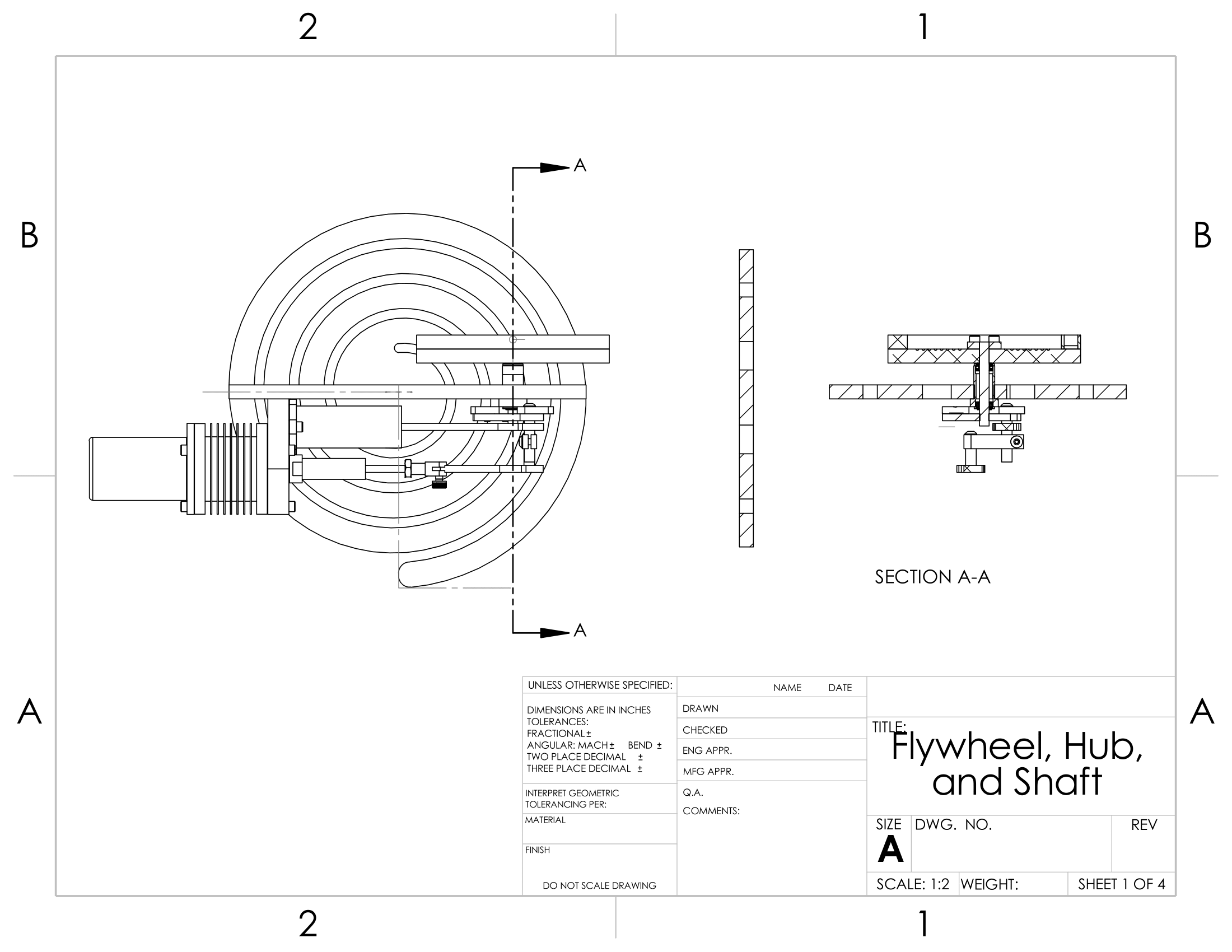
The final engine consisted of these major subassemblies: base and bedplate; flywheel, hub, and balance weight; crankshaft; and piston displacer.
Design Process
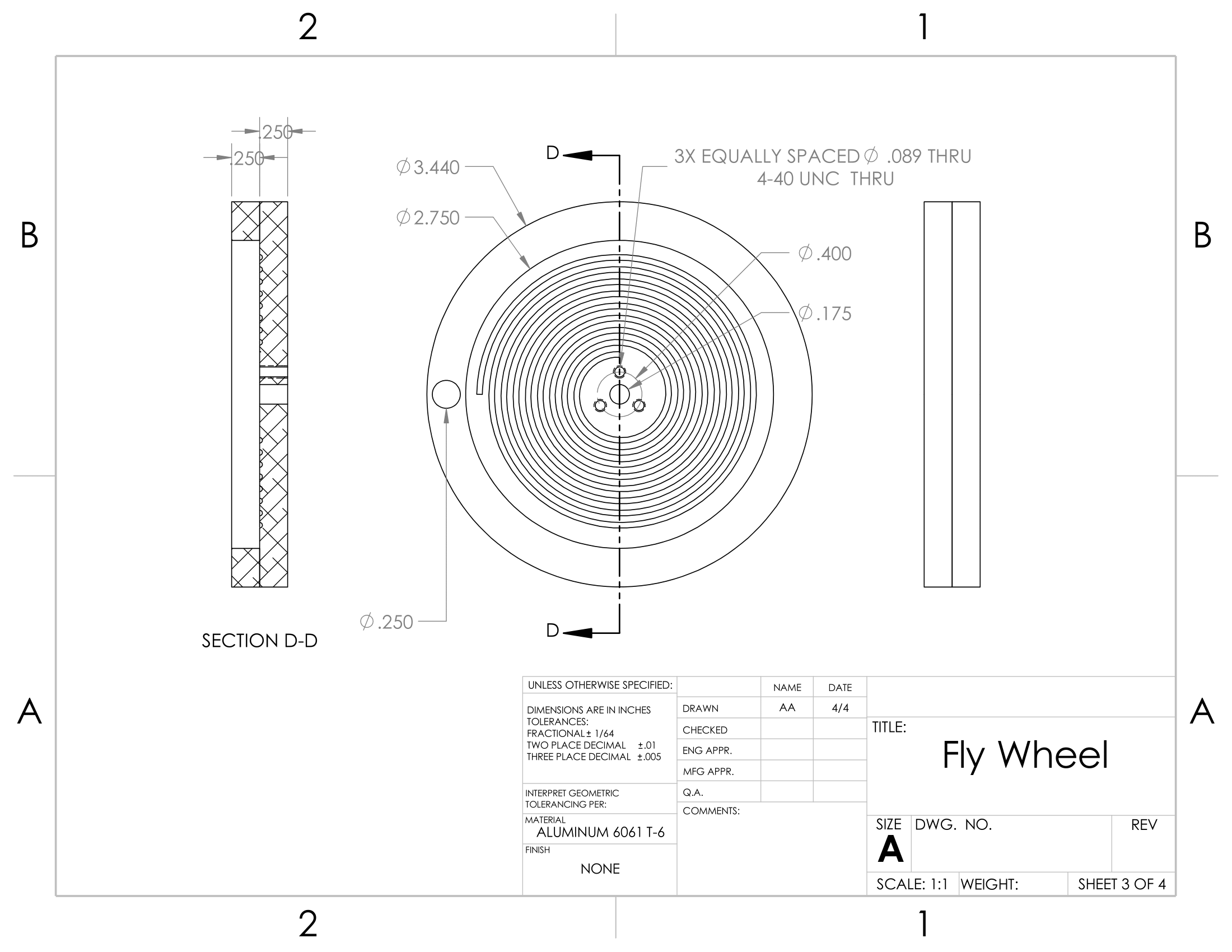
While many of the components were pre-specified, such as the crankshaft and piston parts, the following were custom-designed: flywheel, hub, balance weight, bedplate, and base.
I had no functional requirements with the base, bedplate, and flywheel beyond the mounting holes and basic weight/inertial stability, so I designed them with a spiral motif.
The balance weight was designed using COM analysis in SolidWorks to ensure stability, and the hub was designed to couple the crankshaft and flywheel rotationally.

Flywheel hub and shaft work

Completed flywheel and hub assembly
Technical Takeaways
Design
- Complex CAD Assemblies: Learned to use subassemblies, advanced mates, and COM analysis culminating in a 120+ part assembly file
- Geometric Dimensioning and Tolerancing (GD&T): Learned about and used GD&T principles (form/orientation/location characteristics, datums, and tolerances) to design and dimension parts.
- Tolerance Stackup: Applied tolerance stackup analysis for subcomponents to understand required tolerances in the worst-case scenario.
Manufacturing
- Machining: Gained 60+ hours in the shop with precision manufacturing, milling, turning, and CNC machining.
- Material Choice: Learned characteristics of various materials: 6061-T6 Aluminum, 303 Stainless Steel, and C360 Brass.
Machines Used
- ProtoTRAK Hybrid CNC Mill: Precise cutting and shaping of components.
- Automatic Lathe: Precise turning and drilling of rotationally symmetric parts.
- Drill Press: Rough drilling operations when CNC Mill precision was not required.
- Band Saw: Rough cutting of raw stock to usable dimensions.
Final Project Demo Day
My engine hit around 1700+ rpm after finetuning the displacer length and timing angle.
The engine was powered by heating the displacer casing with a butane microtorch, driving the 4-stroke (heating -> expansion -> cooling -> compression) cycle.
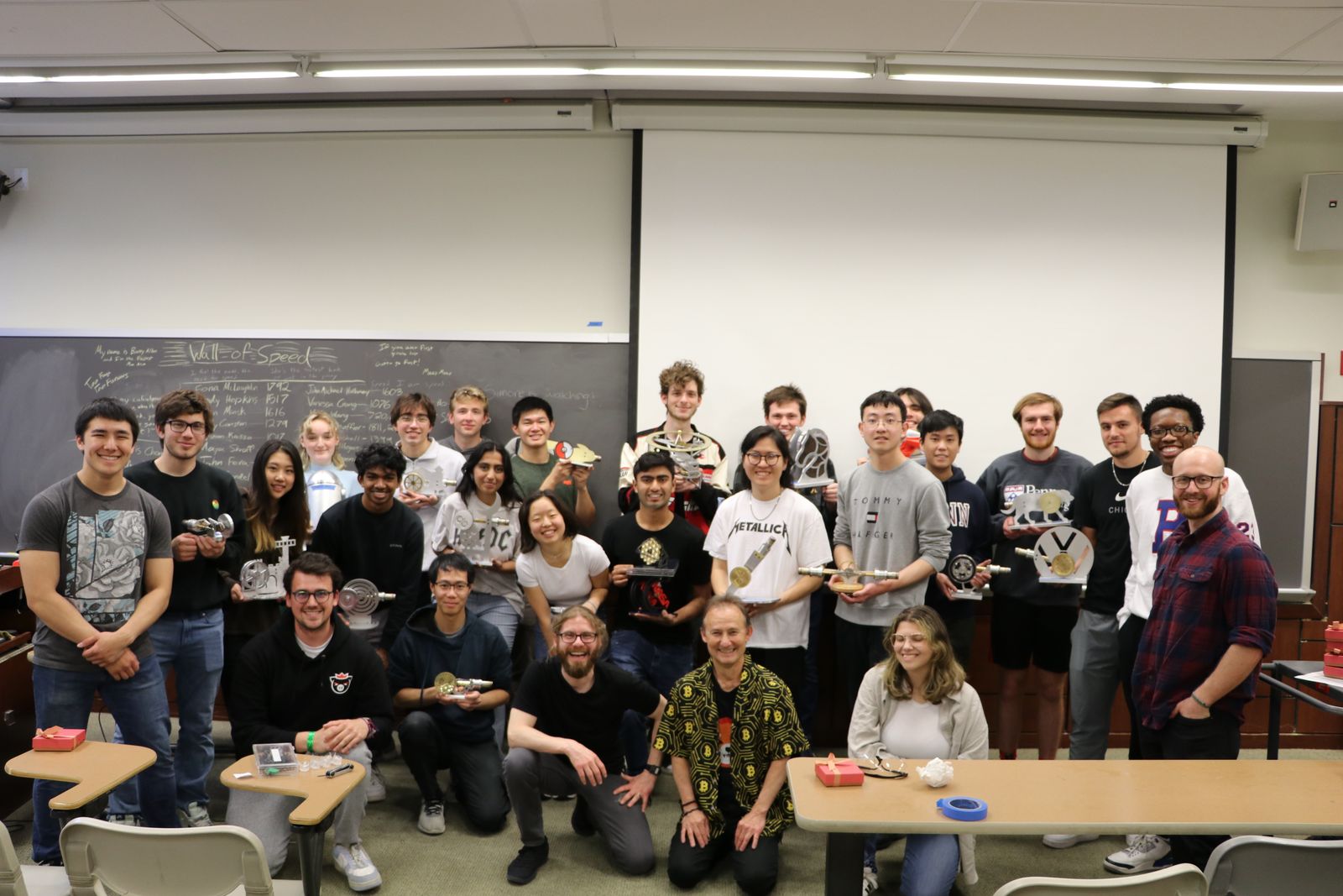
I forgot to record a video of my engine's performance on our final demo day, but here's a wholesome group photo:


